 +33(0)184163232

I2C & Ethernet Reference Design Principle
A Lattice MachXO5T-NX development board or MachXO5-NX development board is used with up to 4 x Pmod I2C Temperature sensors attached.
Each PMOD connector can host two sensor modules.
The design configures the sensors in their most accurate (and slowest) mode (12 bits with a resolution of 1/16th Celsius). The sensors are read 4 times per second.
- The LEDs can display the LSBits of Sensor 0 temperature, or a value written by the PC.
- The LEDs are dimmed by a PWM which can be adjusted by the PC.
- We provide a Python utility program : i2c_eth.py to exercise the FPGA.
- We also provide a command line utility gedek_rw.exe to read and write in the FPGA register map.
The utility programs are available for Windows and Linux.
Block Diagram of the Reference Design

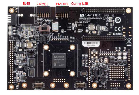
MachXO5T board
The commercial reference of this board is LFMXO5-100T-EVN. The documentation can be found here.

MachXO5-NX board
The MachXO5™-NX Development Board, has a smaller FPGA (-25 instead of -100) and is available in two versions with and without Ethernet ! You need this reference : LFMXO5-25-E-EVN (with Ethernet support). The documentation can be found here.
Testing the Reference Design
All the details can be found in the document below.
You will see how to connect temperature sensors, program the board, connect it to Ethernet and interact with the board from your PC through Ethernet. You’ll see how to visualize the Ethernet frames exchanged using Wireshark.
If you own a LFMXO5-100T-EVN board or a LFMXO5-25-E-EVN board, please contact us so we can send you the latest archive to test this Reference Design.